What it is
Not a tool that builds meshes — one that handles them
Grid Assistant is an offline mesh viewer and CGNS converter with a simple, intuitive interface, and it is free for any use.
Mesh generators each write their own format, and the boundary conditions they leave behind tend to be scattered. Grid Assistant opens what they produced, inspects and tidies it, and writes it back out as a single format: CGNS. It began as a utility for checking and presenting meshes that already exist, with no mesh generation of its own, and has since grown into a light preprocessing tool — renaming boundary patches, scaling, mirroring and the like.
There is no mesh generation. This is not a mesher.
Use cases
What it is used for
Read what a mesh generator produced, in any of the formats below, and write it back out as CGNS.
Rename boundary patches, and merge scattered BC markers into one by name, pattern or type.
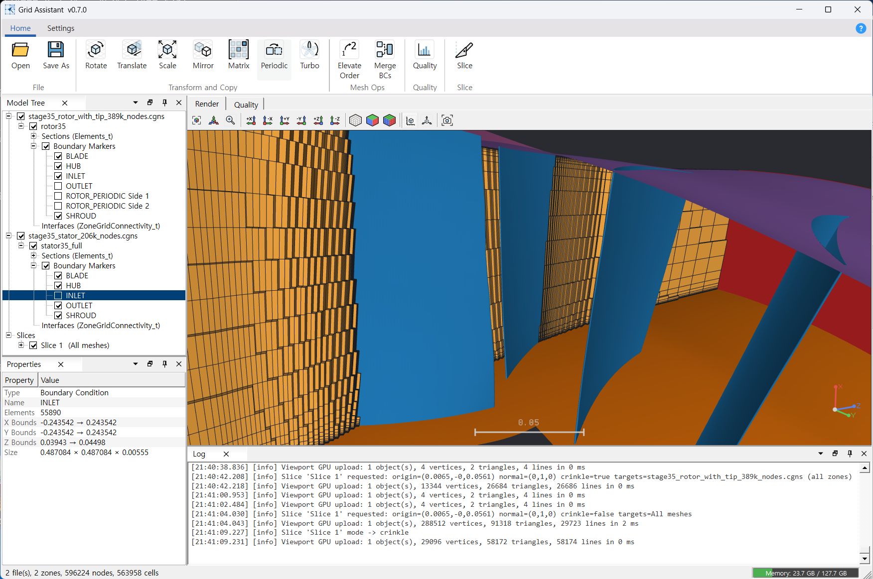
Copy a single turbomachinery passage N times around the circumference to build a full annulus, or weld a half model about its symmetry plane into a full one.
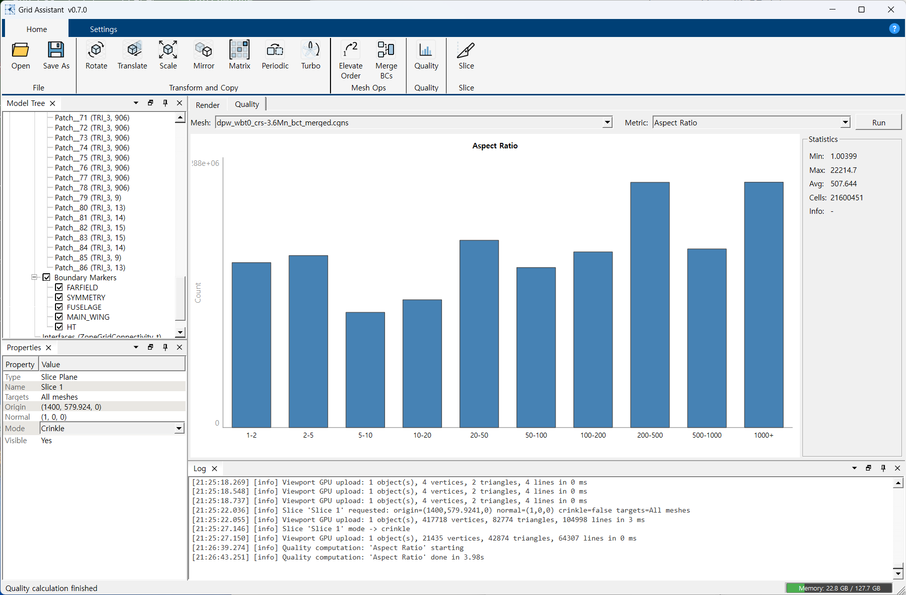
Compute standard metrics — aspect ratio, skewness, scaled Jacobian — to check the mesh before analysis.
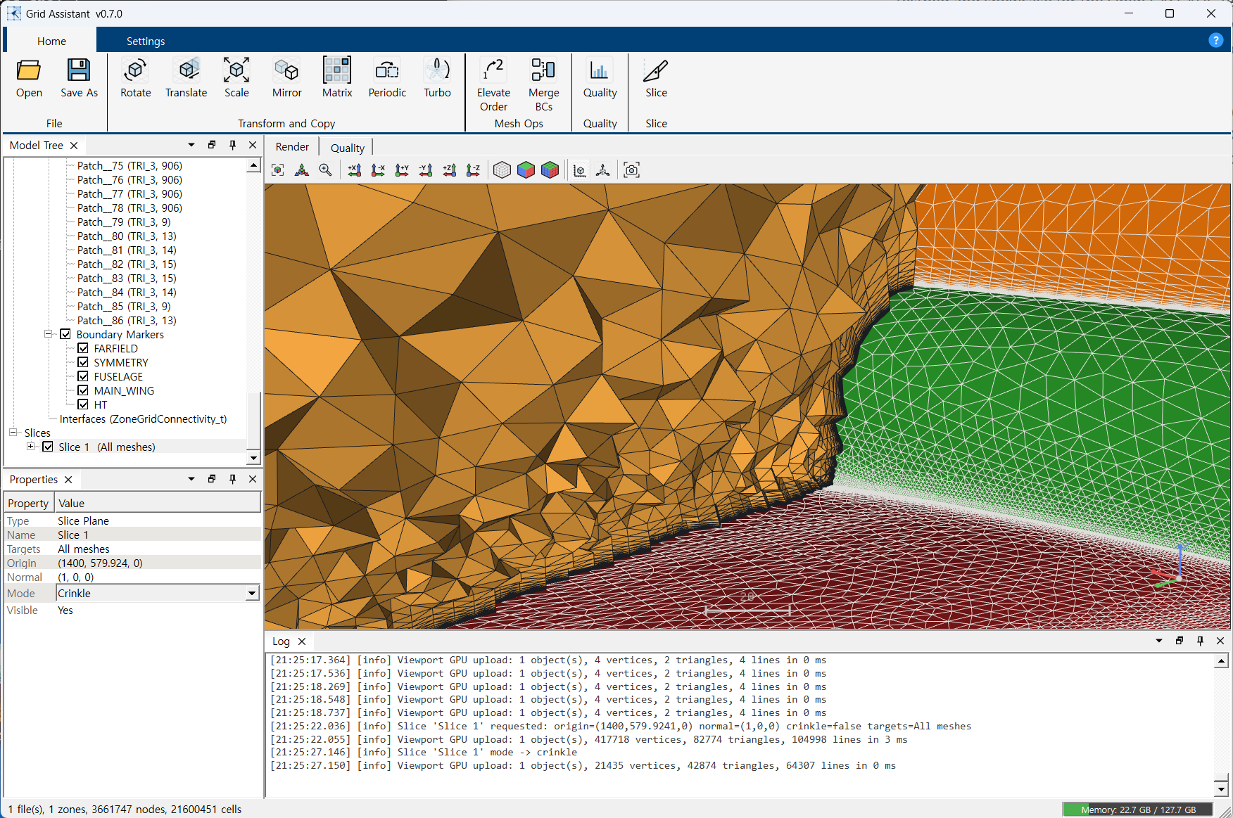
Cut a section on any plane to see the internal geometry.
Align the mesh coordinate system by rotation, translation, scaling, mirroring or an arbitrary 4x4 matrix.
Formats
What it reads and writes
| Format | Extension | Read | Export |
|---|---|---|---|
| CGNS | .cgns | ✓ | HDF5 / ADF |
| SU2 | .su2 | ✓ | — |
| GMSH | .msh | ✓ | — |
| Nastran | .bdf / .nas / .fem | ✓ | — |
| Abaqus | .inp | ✓ | — |
CGNS is currently the only export — Grid Assistant cannot write a mesh back out as SU2, GMSH, Nastran or Abaqus. Fluent .msh files cannot currently be read either.
Workflow
From open to export
- 01 Open
Load the mesh file.
- 02 Inspect
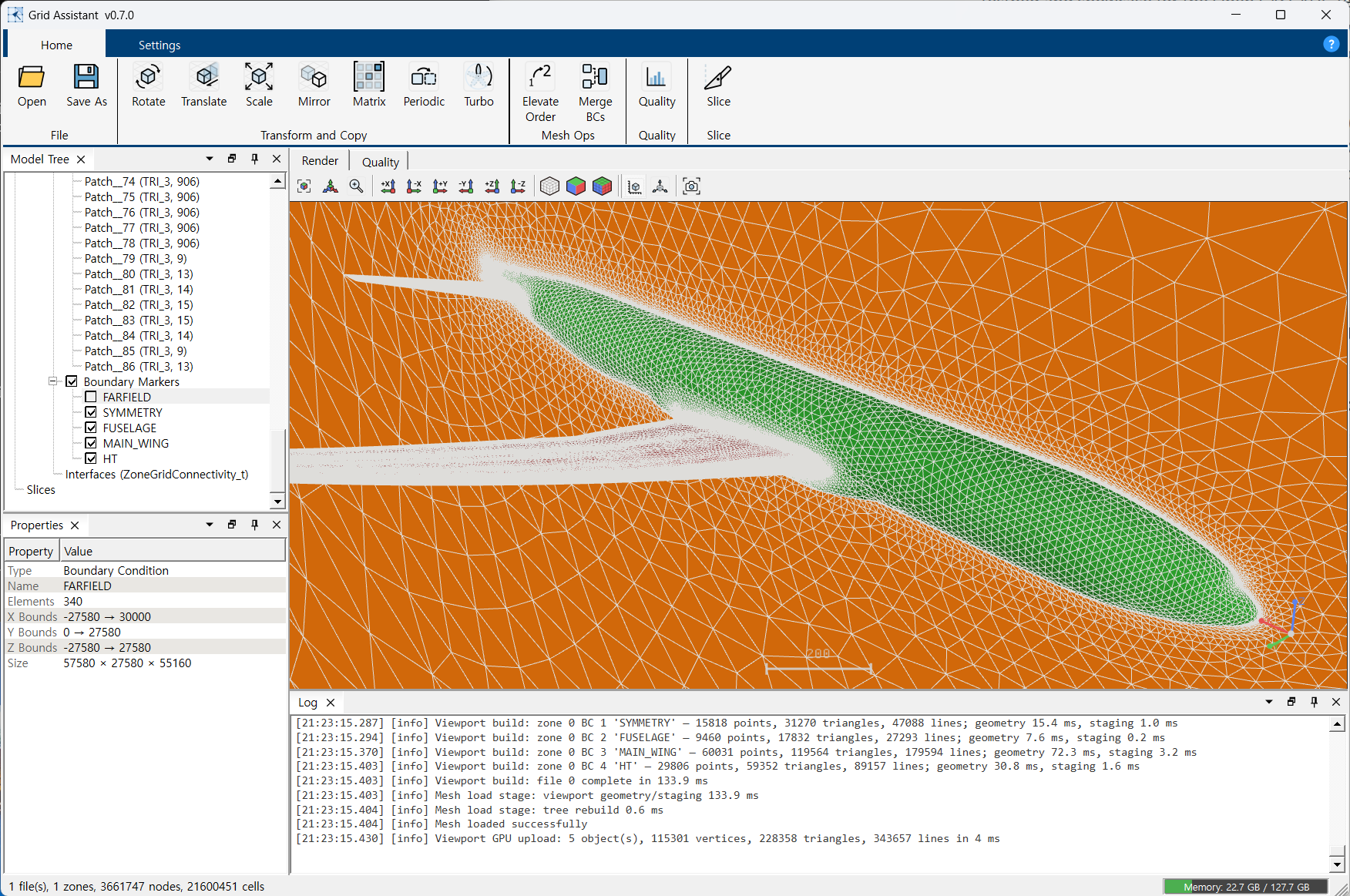
Check the zone, section and BC structure in the Model Tree, and look at the geometry in the 3D view.
- 03 Prepare
Align and duplicate with Transform, tidy boundary conditions with Mesh Ops, and check the mesh with Quality.
- 04 Export
Write the result out as CGNS (HDF5 or ADF).
Quality metrics
- Aspect Ratio Cell aspect ratio — higher means a more stretched cell
- Skewness Cell distortion — 0 to 1, higher is worse
- Scaled Jacobian Cell shape distortion — 0 to 1, lower is worse
- Volume Check Presence of negative volume (inverted) cells
- Non-Orthogonality Non-orthogonality of interior faces — 0 to 90 degrees, higher is worse
Results are given as histograms and statistics; they are not colour-mapped onto the 3D view.
System requirements
Running environment
- Operating system
- Windows 10 / 11 (64-bit)
- Memory
- Scales with mesh size — 8 GB or more recommended for meshes of a few million cells. CGNS files of tens of millions of cells are handled.
- Display
- 1280x800 or larger recommended